
- August 31st, 2020, 2:16 pm
#3741
7000PT (200XX), SM916 (155001/14001), SM5 (150005), Gauntlet (150015)
This document reviews the process of troubleshooting for resistance issues on the Stairmaster Stepmill models listed
above.
Tools Required
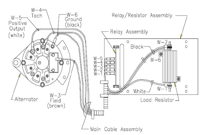
The colored connections to the alternator are as follows:
White-B+ - Alternator output voltage
Brown - Field, Alternator Control Current
Black - Ground, Alternator return
Blue - Tachometer, velocity signal back to console
Resistance over gravity is performed by the alternator in the StepMill. When the console senses a user with staircase movement, the console should be enabling full field current to the alternator. Field current is provided from the external power supply, through the console, into the lower board and wired into the alternator's field terminal. Under this condition, the console should also be driving the lower board's J1 pin 1 low, switching the .Sohm load resistor onto the alternator's B+.
The alternator's B+ should rise as a result of field current, but its voltage will depend on the weight of the user and resulting velocity. Resistance is achieved by the oppositions of internal magnetic fields when field current is applied. The user's weight will affect the alternator's RPM under this condition, and under full field current conditions the voltage is not controlled. But, with the large gear ratio and full field current applied, the resistance should be at maximum, and the step rate should be al a minimum.
Once a user starts a workout, the console controls the alternator's field current attempting to maintain the desired step rate. This signal is Pulse Width Modulated (PWM) from 0V lo 12V, the level of the loaded external supply. If the step rate is fast, the console will deliver field current longer, if the step rate is slow, it will deliver less field current.
The only situation where no field current would be present during a workout is if a very light weight person was attempting lo achieve a step rate that could not be achieved by their weight overcoming the frictional resistance of the system. In this case, the console would keep field current off, or no induced resistance.
During workouts the alternator's B+ increases as a function of speed and user weight. For high level workouts with heavy weight users, B+ levels of 20V could be witnessed.
Power entry is at the bottom of the unit. The 12V 2.5A supply enters via the main power harness, and enters into the PCB via J2. LED2 indicates power is present, but 12V should still be confirmed with a volt meter.
Power and control interface to the console is provided at location J 1. 12V is provided up to the console at J 1 pin 4, and GND pin 5.
In addition to alternator field current, the console controls the loading of the alternator's B+ with the .5 ohm resistor which is switched by the lower board's re lay. When the console detects a user has stepped on the staircase, it immediately applies full field current, and turns on the power relay to load B+ with .5 ohm. LED1 is an indicator the console is attempting to close the relay, but this should be confirmed with a VOM.
If no resistance is felt, confirm 10V to 12V is being applied to the alternator's field. This should always be present once a user is detected, and before a workout has begun. Confirm the additional load is being switched also, which is controlled by a low voltage on J 1 pin 1. The operation of the power relay can be confirmed by unplugging the unit, and removing the console connection at J1. Install external power again, and an ohmmeter should show continuity from B+ to field on the 23545's terminal strip.
Power to unit but no resistance (Staircase freewheels and field LED does not light):
Check alternator brush length:
1. Remove user-right side cover
2. Remove brown wire from W3 (FLD BRN) post of alternator.
3. Loosen ¼” bolts on W3 post.
4. Remove and verify brush length and quality. We recommend replacing brushes that are ¼” or less.
Perform tach test by entering diagnostics, if there is no tach signal from the alternator:
- Check for .6 to .7 volts AC at the W‐4 (Tach) terminal of the alternator.
- If no voltage, remove the blue tach wire from the alternator, while staircase is moving.
Touch the tach wire to the field terminal:
- If the field LED lights, replace the alternator.
- If the voltage checks good, remove the blue connector from the W‐4 (Tach) terminal of the alternator. Lightly scrape the connector and re‐install. Re‐check.
- If still bad, replace the console.
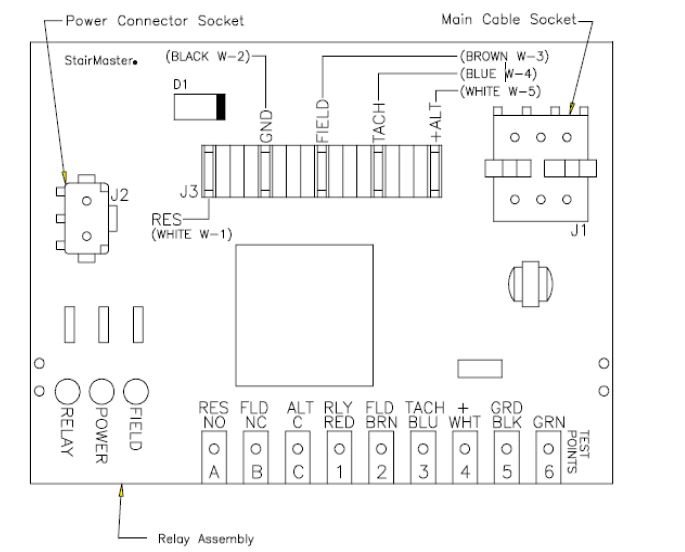
Test relay board:
1. Disconnect the main cable from relay board J1 terminal.
2. With power on, place jumper across GND/BLK and RLY/RED test points. The Relay LED should light. If not, replace lower PCB board.
3. With power on, place jumper across +/WHT and FLD/BRN test points. The Field LED should light. If not, replace lower PCB board.
4. Disconnect the black W-2 ground wire. With power on now, place a jumper on the +/WHT test point and with the other end touch the ALT/C test point, then jump the +/WHT to the FLD/NC test point, and then jump the =/WHT to the RES/NO test point. Once the test is completed, reattach the black W-2 ground wire and the J-1 main cable socket which was removed at the beginning of the relay board test. The Field LED should light. If not, replace lower PCB board.
Other Key Points:
- Remember that the only signal that will prevent the field LED from lighting on the relay board is the tach signal from the blue wire. The console must receive an rpm signal to activate the field current to the alternator that is PWM controlled.
- If you suspect the alternator, disconnect all the wires and check the resistance across the field terminal and the alternator housing; a typical Alternator should read around 4 Ohms or higher.
- The Field LED on the relay board will flicker at higher speed levels. This is the PWM signal from the console to the field terminal of the alternator to control resistance / speed. If you experience full resistance through all levels and the field light doesn’t flicker; replace the console.
- To verify that the load resistor is working correctly, you must ohm the resistor out using your multi meter. The load resistor must read above .5 ohms. If the resistor reads anything less than .5 ohms, then replace the load resistor.
- Always perform mechanical troubleshooting in addition to electrical trouble shooting for resistance problems.
This document reviews the process of troubleshooting for resistance issues on the Stairmaster Stepmill models listed
above.
Tools Required
- Jumper wire
- ½” socket
- ¼” socket
- Multi meter
The colored connections to the alternator are as follows:
White-B+ - Alternator output voltage
Brown - Field, Alternator Control Current
Black - Ground, Alternator return
Blue - Tachometer, velocity signal back to console
Resistance over gravity is performed by the alternator in the StepMill. When the console senses a user with staircase movement, the console should be enabling full field current to the alternator. Field current is provided from the external power supply, through the console, into the lower board and wired into the alternator's field terminal. Under this condition, the console should also be driving the lower board's J1 pin 1 low, switching the .Sohm load resistor onto the alternator's B+.
The alternator's B+ should rise as a result of field current, but its voltage will depend on the weight of the user and resulting velocity. Resistance is achieved by the oppositions of internal magnetic fields when field current is applied. The user's weight will affect the alternator's RPM under this condition, and under full field current conditions the voltage is not controlled. But, with the large gear ratio and full field current applied, the resistance should be at maximum, and the step rate should be al a minimum.
Once a user starts a workout, the console controls the alternator's field current attempting to maintain the desired step rate. This signal is Pulse Width Modulated (PWM) from 0V lo 12V, the level of the loaded external supply. If the step rate is fast, the console will deliver field current longer, if the step rate is slow, it will deliver less field current.
The only situation where no field current would be present during a workout is if a very light weight person was attempting lo achieve a step rate that could not be achieved by their weight overcoming the frictional resistance of the system. In this case, the console would keep field current off, or no induced resistance.
During workouts the alternator's B+ increases as a function of speed and user weight. For high level workouts with heavy weight users, B+ levels of 20V could be witnessed.
Power entry is at the bottom of the unit. The 12V 2.5A supply enters via the main power harness, and enters into the PCB via J2. LED2 indicates power is present, but 12V should still be confirmed with a volt meter.
Power and control interface to the console is provided at location J 1. 12V is provided up to the console at J 1 pin 4, and GND pin 5.
In addition to alternator field current, the console controls the loading of the alternator's B+ with the .5 ohm resistor which is switched by the lower board's re lay. When the console detects a user has stepped on the staircase, it immediately applies full field current, and turns on the power relay to load B+ with .5 ohm. LED1 is an indicator the console is attempting to close the relay, but this should be confirmed with a VOM.
If no resistance is felt, confirm 10V to 12V is being applied to the alternator's field. This should always be present once a user is detected, and before a workout has begun. Confirm the additional load is being switched also, which is controlled by a low voltage on J 1 pin 1. The operation of the power relay can be confirmed by unplugging the unit, and removing the console connection at J1. Install external power again, and an ohmmeter should show continuity from B+ to field on the 23545's terminal strip.
Power to unit but no resistance (Staircase freewheels and field LED does not light):
Check alternator brush length:
1. Remove user-right side cover
2. Remove brown wire from W3 (FLD BRN) post of alternator.
3. Loosen ¼” bolts on W3 post.
4. Remove and verify brush length and quality. We recommend replacing brushes that are ¼” or less.
Perform tach test by entering diagnostics, if there is no tach signal from the alternator:
- Check for .6 to .7 volts AC at the W‐4 (Tach) terminal of the alternator.
- If no voltage, remove the blue tach wire from the alternator, while staircase is moving.
Touch the tach wire to the field terminal:
- If the field LED lights, replace the alternator.
- If the voltage checks good, remove the blue connector from the W‐4 (Tach) terminal of the alternator. Lightly scrape the connector and re‐install. Re‐check.
- If still bad, replace the console.
Test relay board:
1. Disconnect the main cable from relay board J1 terminal.
2. With power on, place jumper across GND/BLK and RLY/RED test points. The Relay LED should light. If not, replace lower PCB board.
3. With power on, place jumper across +/WHT and FLD/BRN test points. The Field LED should light. If not, replace lower PCB board.
4. Disconnect the black W-2 ground wire. With power on now, place a jumper on the +/WHT test point and with the other end touch the ALT/C test point, then jump the +/WHT to the FLD/NC test point, and then jump the =/WHT to the RES/NO test point. Once the test is completed, reattach the black W-2 ground wire and the J-1 main cable socket which was removed at the beginning of the relay board test. The Field LED should light. If not, replace lower PCB board.
Other Key Points:
- Remember that the only signal that will prevent the field LED from lighting on the relay board is the tach signal from the blue wire. The console must receive an rpm signal to activate the field current to the alternator that is PWM controlled.
- If you suspect the alternator, disconnect all the wires and check the resistance across the field terminal and the alternator housing; a typical Alternator should read around 4 Ohms or higher.
- The Field LED on the relay board will flicker at higher speed levels. This is the PWM signal from the console to the field terminal of the alternator to control resistance / speed. If you experience full resistance through all levels and the field light doesn’t flicker; replace the console.
- To verify that the load resistor is working correctly, you must ohm the resistor out using your multi meter. The load resistor must read above .5 ohms. If the resistor reads anything less than .5 ohms, then replace the load resistor.
- Always perform mechanical troubleshooting in addition to electrical trouble shooting for resistance problems.
Stan Saryhin
S-Group Fitness Inc | Exercise equipment repair and service. Residential or Commercial.
http://www.sgroupfitness.com
info@sgroupfitness.com
S-Group Fitness Inc | Exercise equipment repair and service. Residential or Commercial.
http://www.sgroupfitness.com
info@sgroupfitness.com